Boben | Global Leader in Cleanroom Equipment& HEPA Filtration

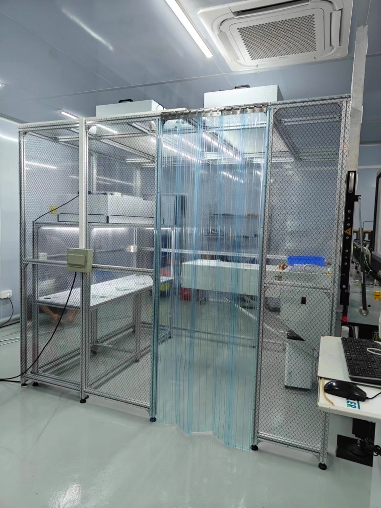
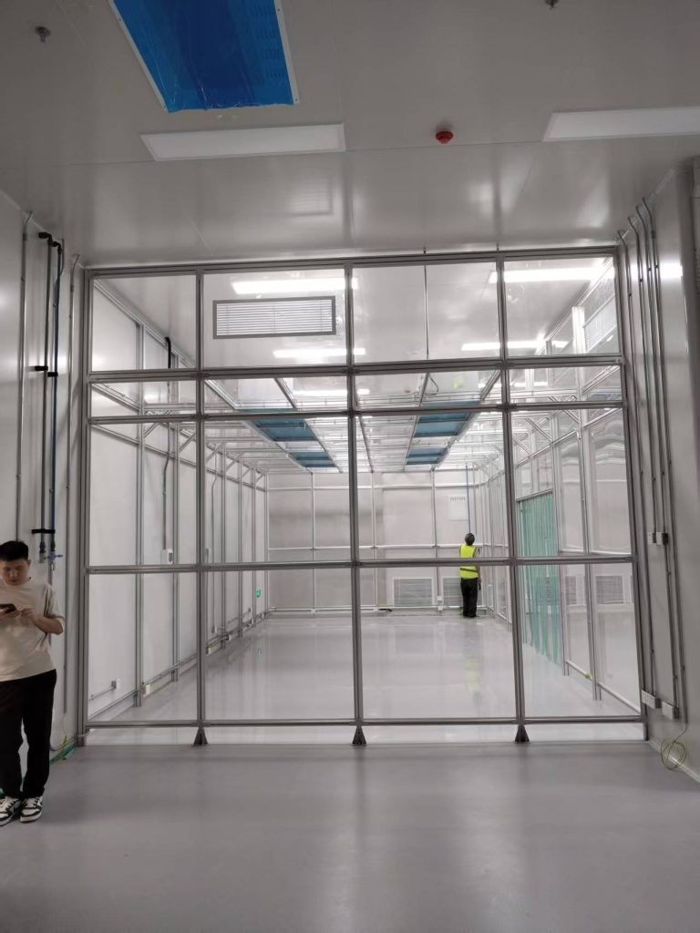
Softwall cleanroom construction plan
As an engineering company with nearly a decade of experience in softwall cleanroom cleanroom construction, we’ve collaborated on softwall cleanroom construction projects for a variety of scenarios, including precision component workshops in electronics factories, pharmaceutical intermediate laboratories, and food freeze-drying production lines. These experiences have taught me a profound understanding: while a cleanroom may seem like simply “building a shed,” it’s actually a systematic project integrating structural mechanics, aerodynamics, and materials science. Oversights in any step can result in substandard cleanroom performance. Below, drawing on practical experience, we’ll analyze this construction plan from preparation to acceptance.
- Project Overview and Objectives
This project involves constructing a Class 10,000 softwall cleanroom (according to GB 50073-2013 standards) for an optical component production workshop. The facility, approximately 100 square meters in area and 3.2 meters in height, houses core equipment areas such as photolithography machines and coating machines. The client’s key requirements were: complete construction within 15 days, ensuring static cleanliness levels ≤ Class 10,000 and ≥ Class 10,000 under dynamic conditions, while also maintaining controlled temperature and humidity (22±2°C, 50±5%RH), and allowing for future equipment expansion.
This type of optical workshop is extremely sensitive to particulate matter. Particles exceeding the standard of 0.5μm can cause lens scratches. Therefore, the design must prioritize the following: ① uniformity of airflow distribution; ② the sealing of the enclosure; and ③ interference with airflow caused by equipment vibration. During the initial site survey, I specifically used a laser particle counter to measure the baseline conditions in the existing workshop. The non-clean area contained approximately 300,000 0.5μm particles per cubic meter. This meant that the softwall cleanroom required a filtration efficiency of at least 97% to achieve these goals.
- Preparation before construction: details determine success or failure
- Design Drawings and Technical Briefing
The plan wasn’t decided on a whim. We first held three coordination meetings with the client and the design team, focusing on confirming three key points:
Airflow Pattern: Considering the high heat generation of the workshop equipment, we ultimately adopted a non-unidirectional flow pattern of “top FFU supply air + side-down return air” (which differs from the high energy consumption of unidirectional flow and is more suitable for medium cleanliness requirements).
Structural Load-bearing Capacity: The original workshop roof load was 300 kg/m2, while the FFU (fan filter unit) + keel + color-coated steel plate weighed approximately 180 kg/m2, meeting the requirements. However, additional reinforcement was required above the equipment area to prevent vibration transmission from the equipment.
Interface Reserve: Water, electricity, and gas lines would be connected from outside the softwall cleanroom. Five 100 mm diameter holes were reserved for conduit entry, which would be sealed with silicone later. This is a detail that many projects often overlook. A previous project consistently failed to meet cleanliness standards during commissioning due to poor sealing of the conduit. During the technical briefing, I took the construction team on-site to review the blueprints using a tape measure and a level: “See? The position of this column must be aligned with the embedded part in the ground. The deviation cannot exceed 5mm. Otherwise, the frame will be crooked, and the color-coated steel plate installed later will leak air.”
- Material Selection and On-Site Inspection
The “frame” and “skin” of a softwall cleanroom directly impact its performance. We selected the following materials:
Main frame: Aluminum profile (80mm × 40mm × 2.5mm), with an oxidized surface treatment, offering three times the rust resistance of ordinary steel.
Enclosure: 50mm thick rock wool sandwich color-coated steel plate (steel plate thickness 0.5mm), with a rock wool density ≥120kg/m³, providing both thermal insulation and fire resistance (Grade A). Each panel must be inspected upon arrival: the color-coated steel plate must be free of scratches (even a 1mm scratch could harbor dust), and the rock wool filling must be evenly distributed (tap on it to listen for the sound; any hollows will be rejected). Purification equipment: I chose a dual-fan model for the FFU (single unit air volume 1500m³/h). The manufacturer provided a test report for the high-efficiency filter (H13 grade). I used a fluorescent pen to illuminate the filter material on site to confirm that there was no damage. I insisted on checking this step myself. Last year, a batch of filters arrived with the outer packaging intact, but when they were unpacked, it was found that the filter material had creases. It took three replacements before it passed the inspection.
- Personnel Training and Site Management
Clean construction differs from ordinary renovations, requiring workers to “use their brains.” We conducted a two-day pre-site training:
Cleanliness Awareness: “Don’t think wearing gloves is inconvenient. Touching the precast steel directly with your hands will cause sweat to corrode the coating, causing it to yellow after three months!”
Operational Standards: Apply sealant in one stroke; do not apply it back and forth (this will create bubbles); tighten keel bolts diagonally to avoid stress concentration; when handling precast steel, two people must lift it evenly; do not apply force on one side (otherwise, it will deform and cause air leakage at the joints).
Safety Instructions: When working at height (over 2 meters), a double-hook safety harness must be worn. Drill and cutting machine cables must be overhead (to prevent them from being stepped on and causing electrical leakage). Two dry powder fire extinguishers are available on site. Last year, a worker cutting square steel had sparks fly onto the rock wool board. Fortunately, the fire extinguisher was readily available, preventing a major disaster.
- Construction Process: From “Establishing the Scaffolding” to “Adjusting the Air”
- Foundation Preparation and Positioning
On the first day on site, we first cleaned the existing ground: vacuuming away gravel and dust (don’t use a broom, it’ll throw up dust!). Then, we used a level to check the ground’s flatness—maximum height difference 15mm. Locally, we applied self-leveling cement (thickness ≤ 5mm). This step is crucial. I often tell the workers, “If the ground is uneven, the columns won’t stand straight. If the columns are crooked, the entire frame will be tilted, and the subsequent installation of the enclosure will be full of gaps, causing air leaks that will make you cry!”
When positioning and marking, we used an ink fountain to mark the centerline of the columns on the ground. Each line was double-checked three times with a tape measure (to an error of ≤ 2mm). After the embedded parts (8mm thick steel plates secured with φ12 expansion bolts) were installed, we used a level to check the flatness of the steel plates. Any unevenness was adjusted with thin iron sheets. This work is as delicate as embroidery, but “more bending in the early stages, less looking up in the later stages”—then the subsequent frame installation will go smoothly.
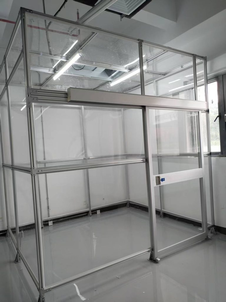
- Frame Construction and Reinforcement
Column installation is crucial for the “skeleton.” We used a forklift to lift the square steel columns (each 3 meters long) onto the embedded components. Workers stabilized them and temporarily secured them. A laser line projector was then used to measure verticality (deviation ≤ 3mm/3m).
When installing the beams, the main beam (connecting the tops of the columns) was installed first, followed by the secondary beams (spaced 1.2 meters apart and used to secure the FFUs). All joints were secured with angle brackets and bolts. After the entire frame was erected, we used infrared to measure the diagonals (the difference between the two diagonals was ≤ 10mm) to ensure that the frame remained stable.
- Enclosure Installation and Sealing
The installation of color-coated steel panels is divided into wall and ceiling panels. Starting from one end, the wall panels are joined using male-female slots. Neutral silicone sealant (8-10mm wide, 3-5mm thick) is applied to the gaps. While applying the sealant, I watched the worker: “Tilt the gun nozzle at a 45-degree angle and apply it at a steady speed. Smooth it with your finger after application—Look, there’s a break in the sealant, it’s leaking! Reapply!” The ceiling panel is more complex, requiring three people: two to lift the panel, and one to hold it in place with the secondary beam. Self-tapping screws are secured (spacing ≤300mm apart), and the screw caps must be covered with sealant to prevent rust and leaks.
Door and window installation is a weak point in sealing. We chose stainless steel airtight doors (with door closers). EPDM sealing strips (30% compression) were used between the door frame and the color-coated steel panels, and the door gap was ≤2mm. When installing the transfer window (double interlocking doors), the frame was flush with the wall panel and sealed with sealant all around.
- Purification System Installation and Commissioning
FFU installation is the heart of the process. First, install an aluminum keel on the secondary beam (to secure the FFU). Use nylon slings to prevent scratching the outer casing when hoisting the FFU. After installation, measure the levelness (deviation ≤ 2mm). The HEPA filter is installed below the FFU and must be aligned and securely pressed. Use sealing strips to press the filter frame against the FFU outlet. Shine a flashlight from the side to confirm there are no leaks. I personally use a flashlight and climb a ladder to check for this step; any leaks require disassembly and reinstallation.
The air duct and return air system are constructed simultaneously. Galvanized steel sheet (0.75mm thickness) is used for the supply duct, and sealant is applied to the joints. The return air duct is installed at the lower wall (300mm height) with a stainless steel grille to prevent rust. During commissioning, the fan is idled for two hours and the wind speed of each FFU is measured (requires ≥ 0.35m/s, with a deviation ≤ 10%). Adjust the inverter for low wind speeds; replace high wind speeds with lower-power fans. Then measure the pressure difference: the pressure difference between the clean room and the non-clean area is ≥15Pa (use a micro pressure differential meter to measure 5 points and take the average value). If the pressure difference is not enough, add FFU or adjust the return air valve.
- Temperature, Humidity, and Dust Particle Testing
Finally, the final test came—the cleanliness test. We selected nine test points (evenly distributed) according to the standard and measured the 0.5μm and 5μm particle counts using a laser particle counter (flow rate of 28.3L/min). Before testing, the system was allowed to run for 24 hours for a “self-cleaning” period. Workers wiped the floor and walls three times with a dust-free cloth and deionized water (from top to bottom to prevent secondary contamination). During the test, everyone wore cleanroom clothing and gloves and stood two meters away from the test point.
I remember that during the first test, the 0.5μm particle count at one point exceeded the standard (12,000 particles/liter). We spent three hours investigating and ultimately discovered a small crack in the sealant on the transfer window, allowing outside air in. After repairs, retesting confirmed that all points met the standard (≤10,000 particles/liter). The temperature and humidity (22°C, 52% RH) also met the requirements, earning a thumbs-up from the owner.
- Quality Control and Safety Assurance
- Quality Control Throughout the Entire Process
We implement a “three-inspection system”: worker self-inspection (checking the seals after each panel is installed), team mutual inspection (the next worker in the process checks the previous one), and dedicated inspection by quality inspectors (using a smoke pen to detect leaks before leaving get off work each day, marking any leaks and requiring corrections the following day). Key milestones (framework acceptance, FFU installation, and cleanliness testing) require on-site signature confirmation from the client’s representative. No further progress is allowed without passing the inspection. A previous project skipped frame inspection to meet deadlines. As a result, the frame sank after the top panel was installed, necessitating dismantling and rebuilding, resulting in a loss of 200,000 yuan.
- Comprehensive Safety Measures
Safety is paramount. Workers are equipped with dust masks (N95 grade), hard hats (to protect against falling objects), and non-slip gloves (to prevent scratches when handling colored steel sheets). For overhead work (top panel and FFU installation), scaffolding (with fully covered scaffolding and 1.2-meter-high guardrails) must be used. Workers must wear double-hook safety harnesses (one hook attached to a fixed point, the other hook moves with the worker). Temporary power is supplied using a “three-level distribution and two-level protection” system. The grounding resistance of the electrical box is ≤4Ω, and the wires are protected with waterproof conduit (to prevent short circuits caused by water). A “five-minute safety meeting” is held before each day’s workday to highlight the day’s risks—for example, wearing goggles when cutting square steel and avoiding getting glue in the eyes when applying it.
- Acceptance and Post-Construction Maintenance Recommendations
- Completion Acceptance Standards
During acceptance, we provided a complete set of documentation: material inspection reports (for color-coated steel plate fire protection and FFU air volume), construction records (for frame verticality and sealant thickness), and test reports (for cleanliness, pressure differential, temperature and humidity). The client requested retesting by a third-party testing agency, and acceptance was considered complete only if all results met the standards.
- Daily Maintenance Key Points
- Cleanrooms are not “set and forget” projects; ongoing maintenance is crucial:
- Monthly: Wipe the FFU housing with a dust-free cloth and inspect the HEPA filter for damage (replace immediately if light leaks occur).
- Quarterly: Measure the pressure differential (if it’s below 10 Pa, inspect the seal or add an FFU). Clean the return air grille (dust accumulation will affect air velocity).
- Annually: Have a professional team conduct a cleanliness test (dynamic environment) and, if necessary, replace the primary filter (pre-filter cotton; clogging will affect FFU air volume).
Conclusion
Looking back on this cleanroom project, we’ve come to a profound understanding: cleanroom engineering relies not on “big moves” but on “small details”—the tightness of a screw, the continuity of a line of sealant, the light leakage of a filter—all can determine success or failure.
Every step in this plan is the result of our own mistakes and the hard work we’ve put into it. We hope it will provide a reference for our peers, and we also hope that all cleanrooms can achieve consistency within their scope and truly safeguard production.
As an engineering company with nearly a decade of experience in cleanroom construction, we’ve collaborated on cleanroom shed construction projects for a variety of scenarios, including precision component workshops in electronics factories, pharmaceutical intermediate laboratories, and food freeze-drying production lines. These experiences have taught me a profound understanding: while a cleanroom may seem like simply “building a shed,” it’s actually a systematic project integrating structural mechanics, aerodynamics, and materials science. Oversights in any step can result in substandard cleanroom performance. Below, drawing on practical experience, we’ll analyze this construction plan from preparation to acceptance.
- Project Overview and Objectives
This project involves constructing a Class 10,000 cleanroom (according to GB 50073-2013 standards) for an optical component production workshop. The facility, approximately 100 square meters in area and 3.2 meters in height, houses core equipment areas such as photolithography machines and coating machines. The client’s key requirements were: complete construction within 15 days, ensuring static cleanliness levels ≤ Class 10,000 and ≥ Class 10,000 under dynamic conditions, while also maintaining controlled temperature and humidity (22±2°C, 50±5%RH), and allowing for future equipment expansion.
This type of optical workshop is extremely sensitive to particulate matter. Particles exceeding the standard of 0.5μm can cause lens scratches. Therefore, the design must prioritize the following: ① uniformity of airflow distribution; ② the sealing of the enclosure; and ③ interference with airflow caused by equipment vibration. During the initial site survey, I specifically used a laser particle counter to measure the baseline conditions in the existing workshop. The non-clean area contained approximately 300,000 0.5μm particles per cubic meter. This meant that the cleanroom required a filtration efficiency of at least 97% to achieve these goals.
- Preparation before construction: details determine success or failure
- Design Drawings and Technical Briefing
The plan wasn’t decided on a whim. We first held three coordination meetings with the client and the design team, focusing on confirming three key points:
Airflow Pattern: Considering the high heat generation of the workshop equipment, we ultimately adopted a non-unidirectional flow pattern of “top FFU supply air + side-down return air” (which differs from the high energy consumption of unidirectional flow and is more suitable for medium cleanliness requirements).
Structural Load-bearing Capacity: The original workshop roof load was 300 kg/m2, while the FFU (fan filter unit) + keel + color-coated steel plate weighed approximately 180 kg/m2, meeting the requirements. However, additional reinforcement was required above the equipment area to prevent vibration transmission from the equipment.
Interface Reserve: Water, electricity, and gas lines would be connected from outside the cleanroom. Five 100 mm diameter holes were reserved for conduit entry, which would be sealed with silicone later. This is a detail that many projects often overlook. A previous project consistently failed to meet cleanliness standards during commissioning due to poor sealing of the conduit. During the technical briefing, I took the construction team on-site to review the blueprints using a tape measure and a level: “See? The position of this column must be aligned with the embedded part in the ground. The deviation cannot exceed 5mm. Otherwise, the frame will be crooked, and the color-coated steel plate installed later will leak air.”
- Material Selection and On-Site Inspection
The “frame” and “skin” of a cleanroom directly impact its performance. We selected the following materials:
Main frame: Aluminum profile (80mm × 40mm × 2.5mm), with an oxidized surface treatment, offering three times the rust resistance of ordinary steel.
Enclosure: 50mm thick rock wool sandwich color-coated steel plate (steel plate thickness 0.5mm), with a rock wool density ≥120kg/m³, providing both thermal insulation and fire resistance (Grade A). Each panel must be inspected upon arrival: the color-coated steel plate must be free of scratches (even a 1mm scratch could harbor dust), and the rock wool filling must be evenly distributed (tap on it to listen for the sound; any hollows will be rejected). Purification equipment: I chose a dual-fan model for the FFU (single unit air volume 1500m³/h). The manufacturer provided a test report for the high-efficiency filter (H13 grade). I used a fluorescent pen to illuminate the filter material on site to confirm that there was no damage. I insisted on checking this step myself. Last year, a batch of filters arrived with the outer packaging intact, but when they were unpacked, it was found that the filter material had creases. It took three replacements before it passed the inspection.
- Personnel Training and Site Management
Clean construction differs from ordinary renovations, requiring workers to “use their brains.” We conducted a two-day pre-site training:
Cleanliness Awareness: “Don’t think wearing gloves is inconvenient. Touching the precast steel directly with your hands will cause sweat to corrode the coating, causing it to yellow after three months!”
Operational Standards: Apply sealant in one stroke; do not apply it back and forth (this will create bubbles); tighten keel bolts diagonally to avoid stress concentration; when handling precast steel, two people must lift it evenly; do not apply force on one side (otherwise, it will deform and cause air leakage at the joints).
Safety Instructions: When working at height (over 2 meters), a double-hook safety harness must be worn. Drill and cutting machine cables must be overhead (to prevent them from being stepped on and causing electrical leakage). Two dry powder fire extinguishers are available on site. Last year, a worker cutting square steel had sparks fly onto the rock wool board. Fortunately, the fire extinguisher was readily available, preventing a major disaster.
- Construction Process: From “Establishing the Scaffolding” to “Adjusting the Air”
- Foundation Preparation and Positioning
On the first day on site, we first cleaned the existing ground: vacuuming away gravel and dust (don’t use a broom, it’ll throw up dust!). Then, we used a level to check the ground’s flatness—maximum height difference 15mm. Locally, we applied self-leveling cement (thickness ≤ 5mm). This step is crucial. I often tell the workers, “If the ground is uneven, the columns won’t stand straight. If the columns are crooked, the entire frame will be tilted, and the subsequent installation of the enclosure will be full of gaps, causing air leaks that will make you cry!”
When positioning and marking, we used an ink fountain to mark the centerline of the columns on the ground. Each line was double-checked three times with a tape measure (to an error of ≤ 2mm). After the embedded parts (8mm thick steel plates secured with φ12 expansion bolts) were installed, we used a level to check the flatness of the steel plates. Any unevenness was adjusted with thin iron sheets. This work is as delicate as embroidery, but “more bending in the early stages, less looking up in the later stages”—then the subsequent frame installation will go smoothly.
- Frame Construction and Reinforcement
Column installation is crucial for the “skeleton.” We used a forklift to lift the square steel columns (each 3 meters long) onto the embedded components. Workers stabilized them and temporarily secured them. A laser line projector was then used to measure verticality (deviation ≤ 3mm/3m).
When installing the beams, the main beam (connecting the tops of the columns) was installed first, followed by the secondary beams (spaced 1.2 meters apart and used to secure the FFUs). All joints were secured with angle brackets and bolts. After the entire frame was erected, we used infrared to measure the diagonals (the difference between the two diagonals was ≤ 10mm) to ensure that the frame remained stable.
- Enclosure Installation and Sealing
The installation of color-coated steel panels is divided into wall and ceiling panels. Starting from one end, the wall panels are joined using male-female slots. Neutral silicone sealant (8-10mm wide, 3-5mm thick) is applied to the gaps. While applying the sealant, I watched the worker: “Tilt the gun nozzle at a 45-degree angle and apply it at a steady speed. Smooth it with your finger after application—Look, there’s a break in the sealant, it’s leaking! Reapply!” The ceiling panel is more complex, requiring three people: two to lift the panel, and one to hold it in place with the secondary beam. Self-tapping screws are secured (spacing ≤300mm apart), and the screw caps must be covered with sealant to prevent rust and leaks.
Door and window installation is a weak point in sealing. We chose stainless steel airtight doors (with door closers). EPDM sealing strips (30% compression) were used between the door frame and the color-coated steel panels, and the door gap was ≤2mm. When installing the transfer window (double interlocking doors), the frame was flush with the wall panel and sealed with sealant all around.
- Purification System Installation and Commissioning
FFU installation is the heart of the process. First, install an aluminum keel on the secondary beam (to secure the FFU). Use nylon slings to prevent scratching the outer casing when hoisting the FFU. After installation, measure the levelness (deviation ≤ 2mm). The HEPA filter is installed below the FFU and must be aligned and securely pressed. Use sealing strips to press the filter frame against the FFU outlet. Shine a flashlight from the side to confirm there are no leaks. I personally use a flashlight and climb a ladder to check for this step; any leaks require disassembly and reinstallation.
The air duct and return air system are constructed simultaneously. Galvanized steel sheet (0.75mm thickness) is used for the supply duct, and sealant is applied to the joints. The return air duct is installed at the lower wall (300mm height) with a stainless steel grille to prevent rust. During commissioning, the fan is idled for two hours and the wind speed of each FFU is measured (requires ≥ 0.35m/s, with a deviation ≤ 10%). Adjust the inverter for low wind speeds; replace high wind speeds with lower-power fans. Then measure the pressure difference: the pressure difference between the clean room and the non-clean area is ≥15Pa (use a micro pressure differential meter to measure 5 points and take the average value). If the pressure difference is not enough, add FFU or adjust the return air valve.
- Temperature, Humidity, and Dust Particle Testing
Finally, the final test came—the cleanliness test. We selected nine test points (evenly distributed) according to the standard and measured the 0.5μm and 5μm particle counts using a laser particle counter (flow rate of 28.3L/min). Before testing, the system was allowed to run for 24 hours for a “self-cleaning” period. Workers wiped the floor and walls three times with a dust-free cloth and deionized water (from top to bottom to prevent secondary contamination). During the test, everyone wore cleanroom clothing and gloves and stood two meters away from the test point.
I remember that during the first test, the 0.5μm particle count at one point exceeded the standard (12,000 particles/liter). We spent three hours investigating and ultimately discovered a small crack in the sealant on the transfer window, allowing outside air in. After repairs, retesting confirmed that all points met the standard (≤10,000 particles/liter). The temperature and humidity (22°C, 52% RH) also met the requirements, earning a thumbs-up from the owner.
- Quality Control and Safety Assurance
- Quality Control Throughout the Entire Process
We implement a “three-inspection system”: worker self-inspection (checking the seals after each panel is installed), team mutual inspection (the next worker in the process checks the previous one), and dedicated inspection by quality inspectors (using a smoke pen to detect leaks before leaving get off work each day, marking any leaks and requiring corrections the following day). Key milestones (framework acceptance, FFU installation, and cleanliness testing) require on-site signature confirmation from the client’s representative. No further progress is allowed without passing the inspection. A previous project skipped frame inspection to meet deadlines. As a result, the frame sank after the top panel was installed, necessitating dismantling and rebuilding, resulting in a loss of 200,000 yuan.
- Comprehensive Safety Measures
Safety is paramount. Workers are equipped with dust masks (N95 grade), hard hats (to protect against falling objects), and non-slip gloves (to prevent scratches when handling colored steel sheets). For overhead work (top panel and FFU installation), scaffolding (with fully covered scaffolding and 1.2-meter-high guardrails) must be used. Workers must wear double-hook safety harnesses (one hook attached to a fixed point, the other hook moves with the worker). Temporary power is supplied using a “three-level distribution and two-level protection” system. The grounding resistance of the electrical box is ≤4Ω, and the wires are protected with waterproof conduit (to prevent short circuits caused by water). A “five-minute safety meeting” is held before each day’s workday to highlight the day’s risks—for example, wearing goggles when cutting square steel and avoiding getting glue in the eyes when applying it.
- Acceptance and Post-Construction Maintenance Recommendations
- Completion Acceptance Standards
During acceptance, we provided a complete set of documentation: material inspection reports (for color-coated steel plate fire protection and FFU air volume), construction records (for frame verticality and sealant thickness), and test reports (for cleanliness, pressure differential, temperature and humidity). The client requested retesting by a third-party testing agency, and acceptance was considered complete only if all results met the standards.
- Daily Maintenance Key Points
- Cleanrooms are not “set and forget” projects; ongoing maintenance is crucial:
- Monthly: Wipe the FFU housing with a dust-free cloth and inspect the HEPA filter for damage (replace immediately if light leaks occur).
- Quarterly: Measure the pressure differential (if it’s below 10 Pa, inspect the seal or add an FFU). Clean the return air grille (dust accumulation will affect air velocity).
- Annually: Have a professional team conduct a cleanliness test (dynamic environment) and, if necessary, replace the primary filter (pre-filter cotton; clogging will affect FFU air volume).
Conclusion
Looking back on this softwall cleanroom project, we’ve come to a profound understanding: cleanroom engineering relies not on “big moves” but on “small details”—the tightness of a screw, the continuity of a line of sealant, the light leakage of a filter—all can determine success or failure.
Every step in this plan is the result of our own mistakes and the hard work we’ve put into it. We hope it will provide a reference for our peers, and we also hope that all cleanrooms can achieve consistency within their scope and truly safeguard production.